Intro to Grasshopper / continued
Download the Zip file: CLASS_03_DIAMONDHOUSE_A
Open your Diamond House A Rhino File from last class, and then open this definition. You will see the definition has been edited as per Assignment 1.2A. We will go through the Louver segment and then also cover modeling stairs.
Editing found Definitions
Download the Zip file: CLASS_03_BRIDGE_REDEFINE
Open this Rhino file + GH File. Here is a more complex modeling example with more design parameters that we have cleaned up from a RhinoCentre file.
You will learn grasshopper, often by editing definitions others have made. We will go through some organization tips such as grouping, arranging, wire display, previewing, and baking.
Original file + demo movie can be found here: http://rhinocentre.blogspot.kr/2011/09/bridge-design-with-grasshopper-for.html
UVA’s Explode_Breps
We will look at UVA’s Explode_Breps website: https://explodebreps.wordpress.com/grasshopper-tutorials/
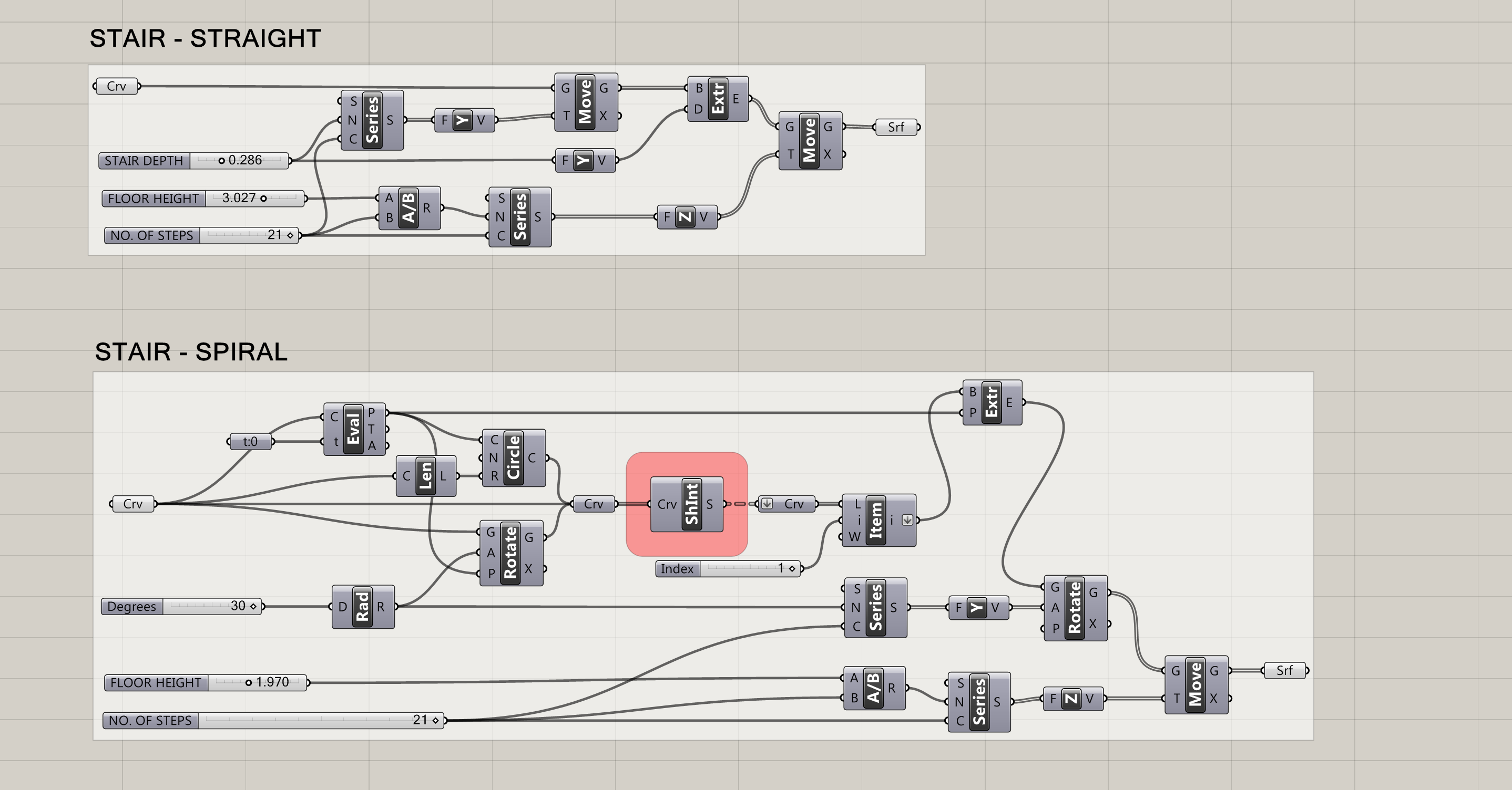
You will see various surface visualization and manipulation definitions, as well as a staircase generator. More advanced students may check out their “variable topographic porosity” definition and/or other surface manipulation definitions. It may be that you model and ultimately 3D print your site with a level of abstraction and manipulation.
Rhino Render
Next, we will go through how to create simple shadow renders to add depth to your drawings. Back in our Diamond House A Rhino file…
Render — Render Properties — DPI – set to 300.
Render — Render Properties — Resolution – You will usually want to increase this from the Default size of 620 x 480, depending on the scale of your output. For today, we will use 1600 x 1200.
Right-click the Perspective Tab in top left-hand corner of your Perspective window, and change from Shaded to Rendered.
Type Sun to view Sun settings. Set Sun On and we will go through the various controls.
Type GroundPlane and set GroundPlane On to render shadows that are on the ground plane.
Parallel View
Right-click the Perspective Tab in top left-hand corner of your Perspective window to look at the Viewport properties. Adjust the Projection from Perspective to Parallel, in order to create an axonometric render. Change Projection back to Perspective when you are finished (it is easier on the eye to model in Perspective view).
You will see when you Make2D your model in axon view, some areas (i.e. where column meets floor slab) may not produce lines. What you can do is select your 3D model and run the intersect command. This will produce curves for all object intersections. Now, when you Make2D your model with these curves included in your selection (with tangent edges checked and hidden lines unchecked in Make2D settings) you should get all your lines.
Saving Views
Right-click the Perspective Tab in top left-hand corner of your Perspective window again. Under Set View, select Named Views. Here you can save your render views, which is useful so that we can also Make2D in the same view, and then combine the image and drawing in Illustrator.
Show Camera (in order to locate your viewpoint in plan)
With cursor active in Perspective View, Select View – SetCamera – Show Camera
Additional Notes
Before rendering, hide the image layer of the house plans.
To render, select Render under the Render tab. Save the rendered image as a .PNG.
To create the Rendered Views in the Plan and Section Cut, we will copy our 3D model and trim the model according to our cuts before rendering.
Open the PNG in Photoshop. Using the Magic Wand Tool we will select the background and delete, and then Save over our file.
After importing your Make2D drawings into Illustrator, you can place your PNG’s in a new layer behind your drawings and adjust the transparency.
In Illustrator, we will go over the Live Paint Bucket (K) command in order to create poches of our plan and section cuts.
1.2B Take-home Assignment: Grasshopper / Diamond House A
Issued: Sept. 18, 2015 / Due: Sept. 25, 2015
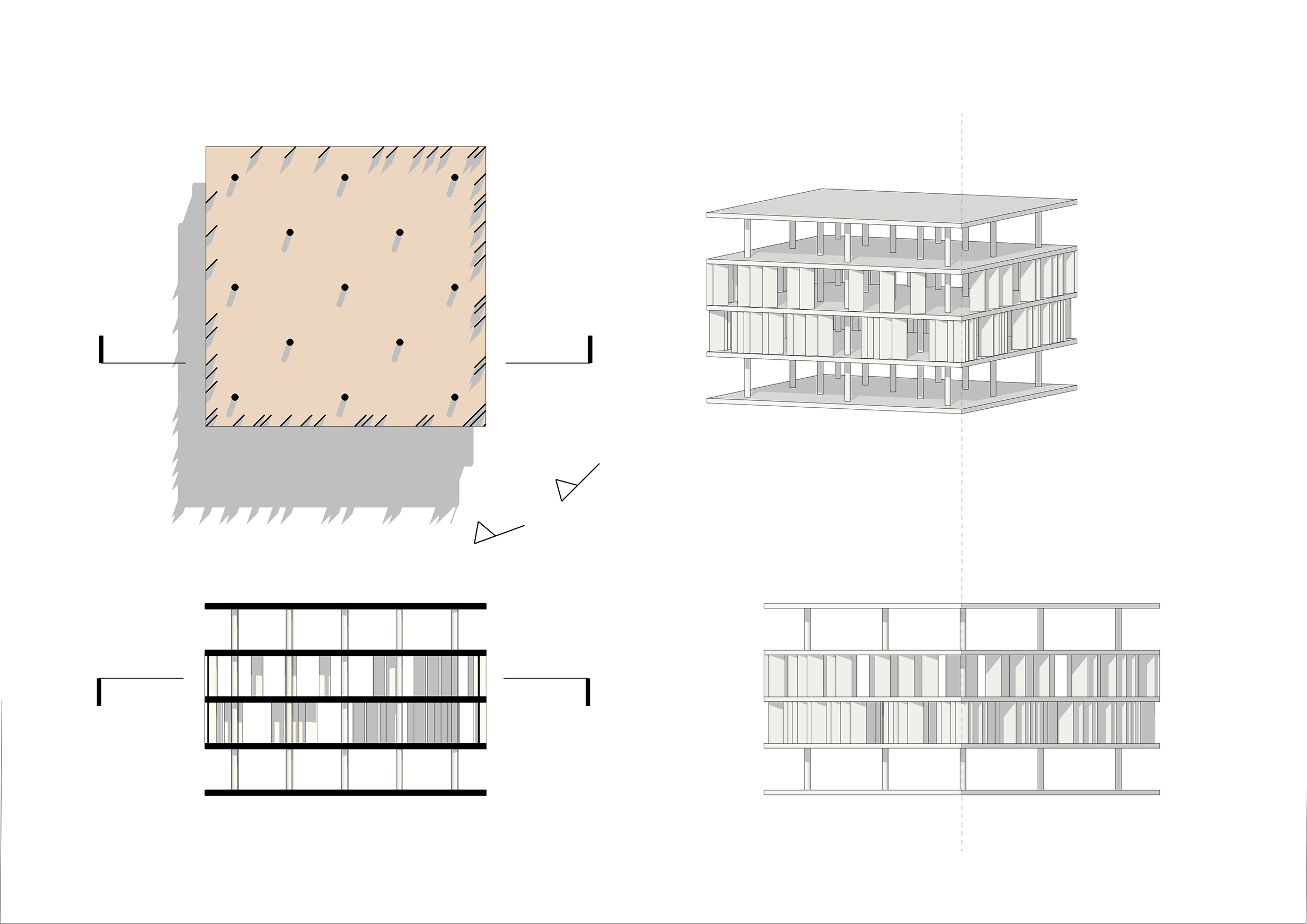
The Diamond House A Grasshopper definition so far has been building the basic repetitive/modular elements of the House. Finish modeling the House in Rhino, i.e. the more idiosyncratic elements (like the curvilinear walls) should be traced and extruded in Rhino.
Produce 1 section cut, 1 plan cut, 1 elevation view and 1 parallel-view drawing with rendered underlays.
Compose your 4 drawings on an A3 sheet at Scale: 1:200, and notate your drawings.
Deliverables:
- Print your 1:200 drawing composition on an A3 sheet and hand them in at the start of the next class.
Additional Practice:
- Edit the definition to distort the house (i.e. irregular floor heights/irregular or alternate rotation of floor plate(s)/alternate density of columns etc.). For advanced students, produce one more drawing sheet to represent your transformed house.
Below is a sample A3 1:200 sheet (unfinished modeling + missing labels). Here rendered images are at 25% opacity.